Magnetic Effects of Electric Current contributes 10–12 marks in CBSE Boards. The diagram and working of an electric motor and AC generator are guaranteed 4–5 mark questions. Fleming's left-hand (motor) and right-hand (generator) rules are standard 1-mark questions. Magnetic field patterns around a straight conductor and a solenoid are diagram favourites. NTSE includes direction-of-force MCQs.
Key Concept Highlights
Magnetic Field and Field Lines
Oersted's Experiment
Magnetic Field Due to Straight Conductor
Right-Hand Thumb Rule
Magnetic Field Due to Circular Loop
Solenoid and its Magnetic Field
Electromagnet
Force on Current-Carrying Conductor in Magnetic Field
Fleming's Left-Hand Rule (Electric Motor)
Electric Motor: Working and Principle
Electromagnetic Induction (Faraday)
Fleming's Right-Hand Rule (Generator)
AC and DC Generator
Domestic Electric Circuits
Important Formulae & Reactions
$F = BIL\ (\text{Force on conductor})\text{ (qualitative)}$
$\text{Fleming's LHR: Force = thumb, Current = middle, Field = index}$
$\text{Fleming's RHR: Motion = thumb, Field = index, Current = middle}$
$\text{Right-hand thumb rule: thumb = current, fingers = field direction}$
$\text{Induced EMF depends on: rate of change of magnetic flux}$
What You Will Learn
◆Draw magnetic field lines around a straight conductor and solenoid
◆Apply right-hand thumb rule to find field direction
◆Apply Fleming's Left-Hand Rule to find force on a conductor
◆Describe the working and diagram of an electric motor
◆Explain electromagnetic induction with Faraday's experiment
◆Describe the difference between AC and DC generators
The three hand rules (right-hand thumb, Fleming's left, Fleming's right) are the core of this chapter — practise them with physical gestures until they are muscle memory. Motor vs generator: motor (electric to mechanical — left hand), generator (mechanical to electric — right hand). CBSE motor diagram question follows a fixed format: show brushes, commutator, armature, magnets. Time investment: 3–4 days.
Chapter 12 · CBSE · Class X
🧲
Magnetic Field and Field Lines
NCERT Class 10 ScienceChapter 12 Magnetic Effects of Electric CurrentMagnetic Field and Field LinesRight Hand Thumb RuleElectromagnetismMagnetic Field Due to CurrentForce on Current Carrying ConductorFleming Left Hand RuleElectric MotorElectromagnetic InductionFleming Right Hand RuleElectric GeneratorDomestic Electric Circuits
📘 Definition
Magnetic Field
A magnetic field is the region in space around a magnet, a current-carrying conductor,
or a moving charge where a magnetic force can be experienced by another magnet or magnetic material.
It is represented by a vector quantity \(\vec{B}\), where:
Direction of \(\vec{B}\) → direction of force on a north pole
Magnitude of \(\vec{B}\) → strength of the magnetic field
SI Unit: Tesla (T)
👁️ Observation
Detection of Magnetic Field
A magnetic field can be detected using a compass needle. When placed in a magnetic field,
the needle aligns itself along the direction of the field.
💡 Concept
Magnetic Field Lines
Magnetic field lines are imaginary curves used to represent the magnetic field.
The tangent at any point gives the direction of the magnetic field.
🏷️ Properties
Key properties of magnetic field lines
Closed loops:
Magnetic field lines always form closed loops. For a bar magnet, they emerge from the
north pole, travel through the surrounding medium, and enter the south pole, then
continue through the magnet’s interior from south to north.
No intersection:
Two magnetic field lines never intersect each other. If they intersected, it would mean
that the magnetic field at the point of intersection has two different directions at the
same time, which is impossible.
Direction indication:
The arrow on a field line shows the direction of the magnetic field. This is the direction
in which the north pole of a small test magnet would move if it were free to do so.
Field strength and crowding:
The density of field lines (how close they are) represents the strength of the magnetic
field. Where field lines are crowded together, the magnetic field is strong; where they
are widely spaced, the field is weak. This is why field lines are denser near the poles of
a bar magnet.
Continuity and smoothness:
Magnetic field lines are smooth, continuous curves; they do not have sharp corners or
breaks. They provide a continuous description of how the magnetic field changes from
point to point.
📌 Note
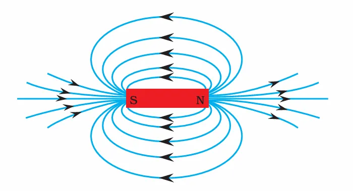
Magnetic Field Lines Around a Bar Magnet
Around a bar magnet:
Outside magnet: field lines go from North → South
Inside magnet: field lines go from South → North
Thus forming closed loops
🖼️ Figure
Field pattern around a bar magnet
Field pattern around a bar magnet
✏️ Example
Why do magnetic field lines never intersect?
Unique direction of magnetic field
If two field lines intersect, the magnetic field at that point would have two directions.
Since direction of a vector quantity is unique, this situation is impossible.
Therefore, magnetic field lines never intersect.
🔢 Formula
Important Relation
\[
B \propto \frac{I}{r}
\]
Magnetic field increases with current and decreases with distance.
⚡ Exam Tip
Always mention "closed loops"
Draw arrows in diagrams
Use proper direction conventions
❌ Common Mistakes
Intersecting field lines
Missing arrows
Wrong direction inside magnet
🌟 Importance
Highly scoring conceptual topic
Frequent diagram questions
Used in assertion-reason questions
🧲
Magnetic Field due to a Current-Carrying Conductor
📘 Definition
When an electric current flows through a conductor, it produces a magnetic field in the
surrounding region. This phenomenon is a direct consequence of moving electric charges.
The magnetic field forms concentric circular loops around the conductor, with the wire
at the center of these circles.
💡 Concept
Concept and Field Pattern
The magnetic field around a straight current-carrying conductor is circular in nature. Each circular
field line lies in a plane perpendicular to the conductor.
Field lines are concentric circles
Center of circles lies on the conductor
Closer to wire → stronger magnetic field
Away from wire → weaker magnetic field
📘 Definition
Right-Hand Thumb Rule
The direction of the magnetic field around a current-carrying conductor is given by the
Right-Hand Thumb Rule.
Hold the conductor in your right hand
Thumb → direction of current
Curled fingers → direction of magnetic field lines
Key Insight: This rule helps determine field direction in numerical and diagram-based questions.
📌 Note
Factors Affecting Magnetic Field Strength
Current (I):
Magnetic field strength increases with increase in current.
Distance (r):
Magnetic field strength decreases as distance from conductor increases.
This relation can be expressed as:
\[
B \propto \frac{I}{r}
\]
📐 Derivation
Derivation of Relation
Experimental observations using iron filings and compass needles show:
Increasing current increases deflection → stronger magnetic field
Increasing distance decreases deflection → weaker magnetic field
Combining both:
\[
B \propto I \quad \text{and} \quad B \propto \frac{1}{r}
\]
Therefore,
\[
B \propto \frac{I}{r}
\]
✏️ Example
What happens to the magnetic field if current is doubled?
Direct proportionality between B and I
Since \(B \propto I\), if current is doubled, the magnetic field strength also doubles.
🛠️ Application
Electric motors
Electromagnets
Transformers
Magnetic sensors
⚡ Exam Tip
Always draw concentric circles in diagrams
Use right-hand thumb rule correctly
State both factors (current and distance)
❌ Common Mistakes
Confusing direction of current and magnetic field
Drawing straight instead of circular field lines
Ignoring dependence on distance
📋 Case Study
A student observes that compass needle deflection increases when current in a nearby wire increases.
Question: Explain why.
Answer:
Magnetic field strength is directly proportional to current. As current increases,
the magnetic field increases, causing greater deflection in the compass needle.
🗒️ Important
Very important for diagrams and numericals
Forms base for electromagnetism
Frequently asked in 3–5 mark questions
🖼️ Figure
Magnetic field around a straight current-carrying conductor
🧲
Right-Hand Thumb Rule (Magnetic Field Direction)
📘 Definition
The Right-Hand Thumb Rule is a fundamental rule used to determine the
direction of the magnetic field around a straight current-carrying conductor.
If a straight conductor is held in the right hand such that the thumb points in the direction of
conventional current, then the curled fingers indicate the direction of the magnetic field lines.
💡 Concept
Conceptual Understanding
Electric current consists of moving charges, and moving charges produce a magnetic field.
The field forms circular loops around the conductor. The Right-Hand Thumb Rule
provides a simple physical method to determine the direction of these loops.
Key Insight: This rule connects current direction with magnetic field direction,
making it essential for diagram-based and reasoning questions.
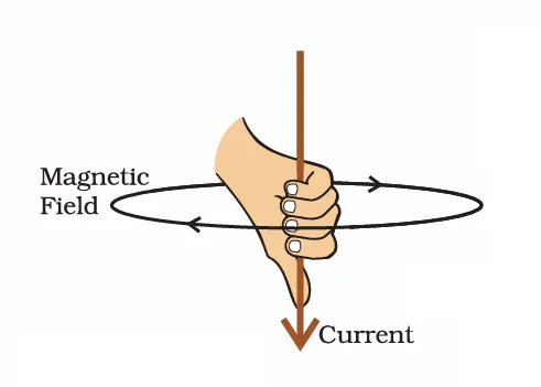
🧠 Remember
Steps to Apply the Rule
1
Imagine holding the conductor with your right hand.
2
Point your thumb in the direction of conventional current (positive → negative).
3
Observe the direction in which your fingers curl — this gives the direction of magnetic field lines.
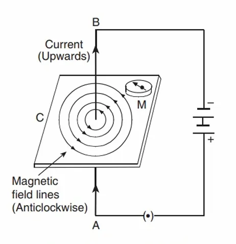
Direction Analysis
Current upward → magnetic field anticlockwise (top view)
Current downward → magnetic field clockwise (top view)
This direction is always perpendicular to the direction of current and forms concentric circles.
🖼️ Figure
Direction of magnetic field using Right-Hand Thumb Rule
📌 Note
Relation with Magnetic Field Formula
The direction obtained from the Right-Hand Thumb Rule complements the magnitude relation:
\[
B \propto \frac{I}{r}
\]
\(\small\mathrm{B}\): magnetic field strength
\(\small\mathrm{I}\): current
\(\small\mathrm{r}\): distance from conductor
✏️ Example
A vertical wire carries current upward. What is the direction of magnetic field when viewed from above?
Apply Right-Hand Thumb Rule
Point the thumb upward (direction of current). The curled fingers move anticlockwise.
Hence, the magnetic field is anticlockwise.
🛠️ Application
Determining direction of magnetic field in wires
Used in electromagnets and solenoids
Foundation for Fleming’s rules
⚡ Exam Tip
Always specify “right hand”, not left hand
Clearly mention thumb = current, fingers = field
Practice top-view and side-view questions
❌ Common Mistakes
Using left hand instead of right hand
Confusing direction of current and field
Forgetting circular nature of field lines
📋 Case Study
A student reverses the direction of current in a conductor.
Question: What happens to the magnetic field direction?
Answer:
When current direction reverses, the direction of the magnetic field also reverses.
This follows directly from the Right-Hand Thumb Rule.
🌟 Importance
Very frequently asked conceptual question
Essential for diagram-based problems
Forms base for advanced rules in magnetism
🧲
Magnetic Field due to Current through a Circular Loop
📘 Definition
When electric current flows through a circular loop of wire, it produces a magnetic field
both around the wire and at the center of the loop. This magnetic field is the result of the combined
effect of magnetic fields due to each small segment of the loop.
💡 Concept
Concept and Field Pattern
Each infinitesimal segment of the circular loop behaves like a small current-carrying conductor and
produces circular magnetic field lines. These individual fields combine to form a resultant magnetic
field:
At the center: magnetic field is maximum and nearly uniform
Inside the loop: field lines are almost parallel and straight
Outside the loop: field lines spread out and become weaker
Key Insight: Increasing the number of turns (coils) increases the magnetic field strength.
📌 Note
Direction of Magnetic Field
The direction of the magnetic field at the center of a circular loop is determined using the
Right-Hand Thumb Rule:
Curl fingers in the direction of current
Thumb points in the direction of magnetic field (along axis of loop)
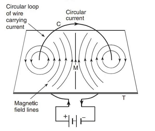
🖼️ Figure
Visualisation
Magnetic field at center is perpendicular to plane
Direction depends on current flow (clockwise/anticlockwise)
Field resembles that of a bar magnet
Magnetic field lines produced by a current-carrying circular loop
🔢 Formula
Important Formulae
Magnetic field at the center of a circular loop:
\[
B \propto \frac{I}{R}
\]
\(B\): magnetic field
\(I\): current
\(R\): radius of loop
For multiple turns:
\[
B \propto \frac{nI}{R}
\]
✏️ Example
What happens to the magnetic field if the radius of the loop is doubled?
Inverse relation with radius
Since \(B \propto \frac{1}{R}\), doubling the radius reduces the magnetic field to half.
🛠️ Application
Electromagnets
Electric motors
Magnetic sensors
Current measuring instruments
⚡ Exam Tip
Always mention "maximum at center"
Use Right-Hand Thumb Rule clearly
Relate to bar magnet field pattern
❌ Common Mistakes
Confusing radius relation (inverse)
Wrong direction using hand rule
Ignoring effect of number of turns
📋 Case Study
A coil is made by winding a wire into multiple circular loops.
Question: Why does it produce a stronger magnetic field?
Answer:
Each loop contributes to the magnetic field. Increasing number of turns increases total field,
making it stronger.
🌟 Importance
Frequently asked conceptual topic
Forms base for solenoid concept
Important for derivations and numericals
🧲
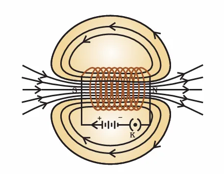
Magnetic Field due to Current in a Solenoid
📘 Definition
Magnetic Field due to Current in a Solenoid
A solenoid is a long cylindrical coil consisting of many closely wound turns of insulated wire.
When electric current flows through it, the solenoid produces a magnetic field similar to that of a
bar magnet.
💡 Concept
Concept and Physical Understanding
Each circular loop of the solenoid contributes to the magnetic field. Due to a large number of turns,
the individual magnetic fields combine to form a strong and nearly uniform magnetic field inside the solenoid.
Key Insight: A solenoid converts electrical energy into magnetic energy efficiently,
forming the basis of electromagnets.
📌 Note
Magnetic Field Pattern
Inside the solenoid: field lines are parallel, straight, and closely spaced
Field inside is strong and uniform
Outside the solenoid: field lines form closed loops
Outside field is weak and non-uniform
🗒️ Visualisation
Magnetic field lines inside and outside a current-carrying solenoid
The uniform spacing of lines inside indicates constant magnetic field strength across the length
of the solenoid.
🗒️ Behavoiur
Behavior like a Bar Magnet
One end behaves as North pole
Other end behaves as South pole
Field pattern resembles that of a bar magnet
🗒️ Direction
Direction of Magnetic Field
The direction of magnetic field inside the solenoid is determined using the
Right-Hand Thumb Rule:
Fingers curl in direction of current in the coil
Thumb points towards the north pole and field direction inside
🔢 Formula
Important Formula
Magnetic field inside a long solenoid:
\[
B \propto nI
\]
\(B\): magnetic field strength
\(n\): number of turns per unit length
\(I\): current
Increasing turns per unit length or current increases magnetic field strength.
🤔 Did You Know?
Factors Affecting Magnetic Field Strength
Number of Turns: More turns increase magnetic field.
Current: Higher current produces stronger field.
Core Material: Soft iron core greatly increases field strength (electromagnet).
✏️ Example
What happens to magnetic field if current is increased?
Direct proportionality
Since \(B \propto I\), increasing current increases magnetic field strength proportionally.
🛠️ Application
Electromagnets
Electric bells
Relays and switches
Magnetic lifting devices (cranes)
⚡ Exam Tip
Always mention "uniform magnetic field inside"
Relate solenoid to bar magnet
State factors affecting field clearly
❌ Common Mistakes
Confusing inside and outside field strength
Ignoring role of core material
Wrong direction using thumb rule
📋 Case Study
A soft iron rod is inserted inside a current-carrying solenoid.
Question: What change occurs in magnetic field?
Answer:
The magnetic field increases significantly because soft iron enhances magnetic permeability,
converting the solenoid into a strong electromagnet.
🌟 Importance
Very important long-answer topic
Frequently asked in diagrams and reasoning
Base for electromagnet applications
🧲
Force on a Current-Carrying Conductor in a Magnetic Field
📘 Definition
When a current-carrying conductor is placed in a magnetic field, it experiences a
magnetic force. This occurs due to the interaction between the magnetic field and the
moving electric charges (current) in the conductor.
💡 Concept
Conceptual Understanding
A current consists of moving charges. When these charges move through a magnetic field, they experience
a force (Lorentz force), which collectively results in a force on the entire conductor.
Key Insight: This phenomenon is the fundamental principle behind electric motors.
🔎 Key Fact
Factors Affecting the Force
Magnetic Field Strength (\(B\)): Stronger field → greater force
Current (\(I\)): More current → more moving charges → greater force
Length of Conductor (\(L\)): Longer conductor → more interaction → greater force
Angle (\(\theta\)): Force depends on orientation with respect to field
🔢 Formula
\[
F = BIL \sin \theta
\]
\(F\): Force on conductor
\(B\): Magnetic field strength
\(I\): Current
\(L\): Length of conductor in field
\(\theta\): Angle between conductor and magnetic field
⭐ Special Case
Maximum force: \( \theta = 90^\circ \Rightarrow F = BIL \)
Zero force: \( \theta = 0^\circ \Rightarrow F = 0 \)
📌 Note
Direction of Force (Fleming’s Left-Hand Rule)
The direction of force is determined using Fleming’s Left-Hand Rule:
Stretch thumb, forefinger, and middle finger mutually perpendicular
Forefinger → direction of magnetic field
Middle finger → direction of current
Thumb → direction of force (motion)
✏️ Example
What happens to the force if current is doubled?
Direct proportionality with current
Since \(F \propto I\), doubling the current doubles the force on the conductor.
🛠️ Application
Electric motors
Loudspeakers
Moving coil galvanometer
Railguns (advanced physics)
⚡ Exam Tip
Always write full formula with sine term
Mention angle condition for max/min force
Use Fleming’s Left-Hand Rule correctly
❌ Common Mistakes
Forgetting \(\sin \theta\)
Confusing left-hand and right-hand rules
Wrong direction interpretation
📋 Case Study
A conductor is placed parallel to a magnetic field.
Question: Will it experience force?
Answer:
No. Since \(\theta = 0^\circ\), \(F = BIL \sin 0 = 0\). Hence, no force acts on the conductor.
🌟 Importance
Very important numerical-based topic
Frequently asked 3–5 mark questions
Core concept behind electric motors
🧲
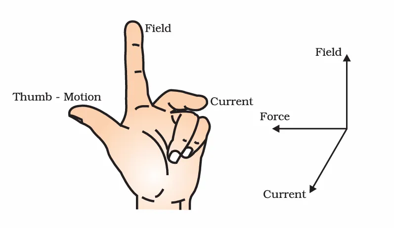
Fleming’s Left-Hand Rule (Motor Rule)
📘 Definition
Fleming’s Left-Hand Rule is used to determine the direction of force (or motion)
experienced by a current-carrying conductor placed in a magnetic field.
It establishes a relationship between magnetic field, current, and
force, all mutually perpendicular to each other.
💡 Concept
When a conductor carrying current is placed in a magnetic field, it experiences a force due to the
interaction between the field and moving charges. The direction of this force is not random but follows
a definite rule — Fleming’s Left-Hand Rule.
Key Insight: This rule is also called the Motor Rule because it explains
the working principle of electric motors.
🤔 Did You Know?
How to Apply the Rule
Stretch the thumb, forefinger, and middle finger of your left hand such that they are
mutually perpendicular (at right angles) to each other.
Forefinger: Direction of magnetic field (N → S)
Middle Finger: Direction of current (positive → negative)
Thumb: Direction of force or motion of conductor
🖼️ Figure
Visualisaton
The three directions are always perpendicular, forming a 3D coordinate relationship:
Field ⟂ Current ⟂ Force
Direction of force using Fleming’s Left-Hand Rule
🔢 Formula
Relation with Force Formula
The magnitude of force is given by:
\[
F = BIL \sin \theta
\]
Fleming’s rule helps determine the direction, while this formula gives the
magnitude.
✏️ Example
A conductor carries current upward in a magnetic field directed from left to right. What is the direction of force?
Apply Fleming’s Left-Hand Rule
Forefinger → right (field), middle finger → up (current). Thumb points out of the plane.
Hence, the force acts outward (towards observer).
🛠️ Application
Electric motors
Moving coil galvanometer
Loudspeakers
Electromechanical devices
⚡ Exam Tip
Always specify "left hand"
Write all three directions clearly
Practice 3D orientation questions
❌ Common Mistakes
Confusing left-hand rule with right-hand rule
Incorrect finger assignment
Ignoring perpendicular nature
📋 Case Study
The direction of current in a motor is reversed.
Question: What happens to the direction of motion?
Answer:
Reversing current reverses the direction of force (thumb direction), hence motion reverses.
🌟 Importance
Very frequently asked conceptual question
Essential for motor-based numericals
Important for diagram and reasoning questions
🧲
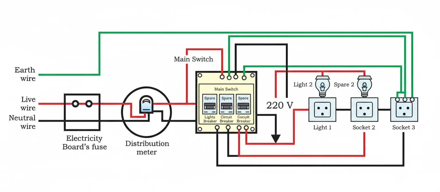
Domestic Electric Circuits (House Wiring System)
📘 Definition
Domestic electric circuits are systems of wiring used in homes to distribute electrical
energy safely from the main supply to various appliances.
These circuits are designed to ensure efficient power distribution, safety, and convenience.
💡 Concept
Concept and Arrangement
In households, appliances are connected in a parallel combination, not in series.
Each appliance gets the same voltage (≈ 220V in India)
Independent operation of devices
Failure of one appliance does not affect others
Key Insight: Parallel connection is essential for proper functioning of household devices.
📌 Note
Components of Domestic Circuits
Live Wire (Phase): Carries current from power supply (usually red/brown)
Neutral Wire: Returns current to the source (usually black/blue)
Earth Wire: Safety wire connected to ground (green) to prevent shocks
Switch: Controls current flow by opening/closing circuit
Fuse / MCB: Protects circuit from overload or short circuit
Energy Meter: Measures electrical energy consumption
🗒️ Key Note
Working Principle
When a switch is turned ON:
Current flows from live wire → appliance → neutral wire
Circuit gets completed and appliance operates
In case of fault:
Excess current flows
Fuse melts or MCB trips
Current stops → prevents damage and fire
🚨 Caution
Earthing (Safety Mechanism)
🚧Caution
Earthing is the process of connecting the metal body of electrical appliances to the ground.
Provides low-resistance path for leakage current
Prevents electric shock
Essential for high-power devices like refrigerators, geysers
Important: Earthing wire is thicker and directly connected to ground.
Fuse and MCB
Fuse
A fuse is a thin wire of low melting point that melts when excess current flows, breaking the circuit.
MCB (Miniature Circuit Breaker)
An MCB automatically trips (switches off) when current exceeds safe limits and can be reset easily.
Fuse → one-time use
MCB → reusable and safer
🖼️ Figure
The diagram shows live and neutral connections with proper earthing for safety.
Schematic diagram of a typical domestic electric circuit
✏️ Example
Why are domestic appliances connected in parallel?
Voltage distribution and independence
In parallel connection, each appliance receives the same voltage and can operate independently.
If one device fails, others continue to work.
⚡ Exam Tip
Always mention parallel connection
Write function of each wire clearly
Differentiate fuse and MCB
❌ Common Mistakes
Confusing live and neutral wires
Ignoring earthing importance
Writing series instead of parallel connection
📋 Case Study
A short circuit occurs in a household appliance.
Question: What safety device prevents damage?
Answer:
The fuse melts or the MCB trips, breaking the circuit and preventing overheating or fire.
🌟 Importance
Highly important theory-based topic
Frequently asked in 3–5 mark questions
Important for real-life application questions
🧲
Important Points: Magnetic Effects of Electric Current
🗒️ Body
Quick Revision Notes
A compass needle is a tiny bar magnet. The end pointing towards geographic north is
called the north pole, and the opposite end is the south pole.
A magnetic field exists in the space around a magnet where its influence can be
detected. It is represented by vector \(\vec{B}\).
Magnetic field lines represent the magnetic field. They show:
Direction of field (tangent at any point)
Strength (density of lines)
Field lines are closer where the field is strong and farther apart where the field is weak.
They form closed loops and never intersect.
A current-carrying conductor produces a magnetic field with
concentric circular field lines, whose direction is given by the
Right-Hand Thumb Rule.
The magnetic field pattern depends on the shape of the conductor:
Straight wire → circular field
Circular loop → strong field at center
Solenoid → uniform field like a bar magnet
A solenoid produces a magnetic field similar to a bar magnet with distinct
north and south poles.
An electromagnet consists of a soft iron core wrapped with insulated copper wire.
It produces a strong magnetic field when current flows.
A current-carrying conductor placed in a magnetic field experiences a
force, given by:
\[
F = BIL \sin \theta
\]
The direction of this force is determined using
Fleming’s Left-Hand Rule, where:
Forefinger → magnetic field
Middle finger → current
Thumb → force
In domestic supply, we receive 220 V AC, 50 Hz. The wires are:
Live (Red/Brown): carries current
Neutral (Black/Blue): returns current
Earth (Green): safety wire
Earthing protects users by providing a low-resistance path for leakage current,
preventing electric shock.
A fuse is a safety device that melts when excess current flows, protecting the circuit
from damage due to overloading or short-circuiting.
⚡ Exam Tip
Always mention "closed loops" for magnetic field lines
Right-hand rule and Fleming’s rule are frequently asked
Domestic circuit diagrams are very important
Formula-based questions (force) carry high weightage
NCERT Class X · Chapter 12
Magnetic Effects of Electric Current
A comprehensive AI-powered learning engine — concepts, formulas, solver, practice questions, and interactive labs. No login required.
Core Concepts
Click any concept card to explore it in depth with explanations, diagrams, and key ideas.
01 · Foundation
Magnetic Field & Field Lines
A region around a magnet where magnetic force is experienced. Field lines give a visual map of direction and strength.
Field LinesDirectionProperties
02 · Oersted's Discovery
Magnetic Effect of Current
Hans Christian Oersted found that a current-carrying conductor deflects a nearby compass needle, proving electricity creates magnetism.
Oersted 1820Current → B
03 · Straight Conductor
B due to Straight Wire
A straight current-carrying wire produces concentric circular field lines. Direction is given by the Right Hand Thumb Rule.
RHTRConcentric CirclesB ∝ I / r
04 · Circular Coil
B due to Circular Loop
Each small arc of a current loop contributes to a net field at the centre. Multiple turns amplify the effect proportionally.
Loop CentreB ∝ nI/r
05 · Solenoid
Solenoid & Bar Magnet Analogy
A solenoid is a coil of insulated wire; its field resembles a bar magnet. One end acts as N-pole, the other as S-pole.
Bar MagnetUniform Field Inside
06 · Force on Conductor
Force on Current-Carrying Wire
A current-carrying conductor in an external magnetic field experiences a force. Fleming's Left Hand Rule gives the direction.
Fleming's LHRF = BIL sinθ
07 · Electric Motor
Principle of Electric Motor
Uses magnetic force on current-carrying coil to produce rotation. Split ring commutator ensures continuous rotation.
RotationCommutatorArmature
08 · Electromagnetic Induction
Faraday's Law & Lenz's Law
Changing magnetic flux through a coil induces an EMF. The induced current opposes the change (Lenz's Law).
FaradayLenz's LawFleming's RHR
09 · Electric Generator
AC & DC Generators
Converts mechanical energy to electrical energy using electromagnetic induction. AC uses slip rings; DC uses split ring commutator.
AC GeneratorDC Generator
10 · Household Circuits
Domestic Electric Circuits & Safety
Live, neutral, and earth wires. Fuse and MCB protect against overloading. Earthing prevents electric shock.
Fuse / MCBEarthingSafety
Magnetic Field & Field Lines
ℹ️
A magnetic field is a region in space where a magnetic force is experienced. It is represented by magnetic field lines.
Properties of Magnetic Field Lines
1. They emerge from the N-pole and enter the S-pole outside the magnet, forming continuous closed loops.
2. They never intersect each other — two field lines at the same point would imply two directions of force, which is impossible.
3. Closer field lines → stronger field; wider apart → weaker field.
4. They are always perpendicular to the surface of the magnet at its poles.
5. Inside the magnet, they travel from S-pole to N-pole.
⚠️
Magnetic field lines do not have a start or end — they form closed loops (unlike electric field lines which start on +q and end on −q).
SI Unit & Symbol
Magnetic field strength B is measured in Tesla (T). Older unit: Gauss (G). 1 T = 10,000 G. The direction of B at a point is the direction a free N-pole would move when placed there.
Oersted's Experiment & Magnetic Effect of Current
🔬
In 1820, Hans Christian Oersted discovered that a current-carrying conductor deflects a magnetic compass needle placed near it — the first proof that electricity and magnetism are related.
The Experiment
A compass needle is placed parallel to a current-carrying wire. When current flows: • The needle deflects perpendicular to the wire. • On reversing the current, the needle deflects in the opposite direction. • When the current is switched off, the needle returns to its original position.
Significance
Established the link between electricity and magnetism. Led to the development of electromagnetism as a unified science. The effect is called the magnetic effect of electric current.
B due to Straight Current-Carrying Conductor
📐
A straight current-carrying wire produces concentric circular magnetic field lines centred on the wire.
Right Hand Thumb Rule (RHTR)
Imagine holding the wire in the right hand with the thumb pointing in the direction of current. The curled fingers indicate the direction of circular magnetic field lines around the wire.
Factors Affecting B
• B ∝ I — Doubling the current doubles B. • B ∝ 1/r — As distance from wire increases, B decreases. • B is strongest closest to the wire.
🔄
Reversing the current reverses the direction of the magnetic field lines.
B due to Circular Current Loop
⭕
At the centre of a circular current loop, all the curved field lines from each arc segment add up in the same direction, producing a net uniform magnetic field.
Key Relationships
• B ∝ I — More current → stronger field at centre. • B ∝ n — More turns → field multiplied n times. • B ∝ 1/r — Smaller radius → stronger field at centre.
Direction of Field at Centre
Use the Right Hand Thumb Rule for each small arc. Curl right-hand fingers in the direction of current around the loop. The thumb points in the direction of B at the centre.
• Current anticlockwise (when viewed from front) → N-pole faces you (field emerges). • Current clockwise → S-pole faces you (field enters).
Solenoid & Bar Magnet Analogy
🧲
A solenoid is a long coil of insulated copper wire wound in close turns. The field inside is strong, uniform, and parallel to the axis — identical to a bar magnet's field.
Properties
• The field inside a solenoid is uniform and parallel to its axis. • Outside the solenoid, the field is similar to a bar magnet. • One end becomes N-pole and the other S-pole depending on the direction of current. • The field strength can be increased by: (i) increasing current, (ii) increasing number of turns per unit length, (iii) inserting a soft iron core (making it an electromagnet).
Electromagnet Applications
Cranes for lifting iron scrap, electric bells, MRI machines, electromagnetic relays, circuit breakers. An electromagnet can be switched on/off, making it versatile.
Force on a Current-Carrying Conductor in a Magnetic Field
⚡
When a current-carrying conductor is placed in an external magnetic field, it experiences a mechanical force — this is the basis of the electric motor.
Fleming's Left Hand Rule (FLHR)
Stretch the forefinger, middle finger, and thumb of the left hand mutually perpendicular: • Forefinger → direction of magnetic field (B) • Middle finger → direction of current (I) • Thumb → direction of force / motion (F)
Magnitude of Force
F = B × I × L × sinθ where θ is the angle between the current and B. • F is maximum when θ = 90° (conductor perpendicular to B). • F = 0 when θ = 0° or 180° (conductor parallel to B).
Electric Motor
⚙️
An electric motor converts electrical energy → mechanical energy. It is used in fans, mixers, washing machines, electric trains.
Key Components
1. Armature — rectangular coil of wire (ABCD) that rotates between poles. 2. Permanent Magnet — provides the external B field. 3. Split Ring Commutator — two halves of a ring that reverse the direction of current in the coil every half rotation, ensuring continuous rotation in the same direction. 4. Brushes — carbon brushes maintain electrical contact with the rotating commutator.
Working Principle
• Current in arm AB flows from A to B; current in arm CD flows from C to D. • By FLHR, AB experiences upward force and CD downward force → coil rotates. • After half rotation, commutator reverses the current → forces remain in same direction → continuous rotation.
Electromagnetic Induction — Faraday & Lenz
💡
Electromagnetic Induction: When the magnetic flux through a circuit changes, an EMF (and hence current) is induced in the circuit. Discovered by Michael Faraday in 1831.
Ways to Induce Current
1. Moving a bar magnet into/out of a coil. 2. Changing the current in a nearby coil (mutual induction). 3. Rotating a coil in a magnetic field. 4. Changing the strength of external B field.
Lenz's Law
The induced current always flows in a direction such that it opposes the change in magnetic flux that caused it. This is a consequence of conservation of energy — if the induced current aided the change, it would create energy from nothing!
Fleming's Right Hand Rule (for generators)
Stretch right hand's forefinger (B direction), thumb (motion of conductor), and middle finger (induced current direction) mutually perpendicular. The middle finger gives the direction of induced current.
AC & DC Generators
🔋
A generator converts mechanical energy → electrical energy using electromagnetic induction. It is the reverse of an electric motor.
AC Generator
• Uses slip rings — each end of the coil is connected to a separate ring. • Brushes press against the rings and take current to the external circuit. • As the coil rotates, current in the external circuit alternates in direction every half turn → Alternating Current (AC). • In India: AC frequency = 50 Hz, voltage = 220 V.
DC Generator
• Uses a split ring commutator (like the motor). • The reversal of current in the coil is synchronised with the commutator reversal, so external circuit always gets current in the same direction → Direct Current (DC). • Batteries and cells produce DC.
⚡
AC is preferred for long-distance power transmission because voltage can be stepped up/down easily using transformers — minimising energy loss in transmission lines.
Domestic Electric Circuits & Safety
🏠
In India, domestic supply is 220 V AC at 50 Hz. Three wires are used: live (red/brown), neutral (black/blue), and earth (green/yellow).
The Three Wires
• Live wire — carries alternating current at 220 V. • Neutral wire — returns current; at earth potential (0 V). • Earth wire — connected to a metal plate buried in the ground; safety wire that provides a path of least resistance in case of fault.
Fuse & MCB
• Fuse: A thin wire of low melting point alloy in series with the live wire. If current exceeds the rated value, the wire melts and breaks the circuit. • MCB (Miniature Circuit Breaker): An automatic switch that trips when current exceeds a set value. Can be reset — more convenient than replacing a fuse wire.
Short Circuit & Overload
• Short circuit: Live and neutral wires touch directly (very low resistance → very high current). • Overloading: Too many high-power appliances connected simultaneously → total current exceeds safe limit. Both are dangerous and are prevented by fuses/MCBs.
All Key Formulas
Every formula from Chapter 12 with variable legend and usage notes.
B · Straight Wire
B ∝ I / r
Magnetic field at perpendicular distance r from a long straight wire carrying current I.
I = current (A)r = distance (m)B = field (T)
B · Circular Loop
B ∝ nI / r
Magnetic field at the centre of a circular loop of n turns, radius r, carrying current I.
n = turnsI = current (A)r = radius (m)
Force on Wire
F = BIL sinθ
Force on a straight conductor of length L carrying current I in field B, at angle θ to the field.
B = field (T)I = current (A)L = length (m)θ = angle
Max Force (θ=90°)
F = BIL
Maximum force when conductor is perpendicular to B (sin 90° = 1). Minimum (F=0) when parallel to B.
B = field (T)I = current (A)L = length (m)
Electrical Power
P = VI = I²R
Power consumed by an appliance. Heat generated in fuse wire determines its rating.
V = voltage (V)I = current (A)R = resistance (Ω)
Fuse / Safe Current
I = P / V
Current drawn by an appliance. Used to find safe fuse rating for a circuit.
P = power (W)V = voltage (V)
Faraday's EMF
ε = −dΦ/dt
Induced EMF equals the negative rate of change of magnetic flux (conceptual — no derivation at Class X).
ε = induced EMF (V)Φ = flux (Wb)
Ohm's Law
V = IR
Applied to analyse domestic circuit loads and determine fuse ratings.
V = voltage (V)I = current (A)R = resistance (Ω)
Hand Rules — Quick Reference
👍
RHTR (B direction for straight wire) Thumb = current direction; fingers curl in B direction.
🤚
FLHR (Force on conductor / Motor) Left hand: Forefinger=B, Middle=I, Thumb=F.
✋
FRHR (Induced current / Generator) Right hand: Forefinger=B, Thumb=motion, Middle=I_induced.
Step-by-Step AI Solver
Select a problem type, enter known values, and get a fully worked solution.
ℹ️
For two parallel wires: like currents (same direction) attract; unlike currents (opposite) repel. No numerical calculation needed — select direction below.
✔ Solution
Practice Questions
Concept-building questions with complete step-by-step solutions — never from the textbook directly.
Q01
Two magnetic field lines are shown crossing each other at a point. Explain why this situation is physically impossible.
EasyField Lines
+
1
Recall the definition: a magnetic field line at any point gives the direction in which a free N-pole would move.
2
If two field lines cross at point P, there would be two different tangent directions at P — implying two different directions of magnetic force at the same point.
3
A free N-pole cannot move in two directions simultaneously at the same point — this is a physical contradiction.
∴ Magnetic field lines can never intersect each other.
Q02
A compass is held near a vertical wire. When current flows upward, the N-pole of the compass deflects east. What happens if (a) current is doubled and (b) current direction is reversed?
MediumStraight Wire
+
1
By RHTR: current upward → B circles anticlockwise when viewed from above. At the east side of the wire, B points south → free N-pole moves east (given).
2
(a) Doubling current doubles B (B ∝ I). The compass deflects east more strongly but direction remains east.
3
(b) Reversing current makes it flow downward → B direction reverses everywhere → at the east side, B now points north → free N-pole is deflected west.
(a) Deflection increases; direction remains east. (b) N-pole deflects west.
Q03
A wire of length 0.4 m carrying a current of 3 A is placed perpendicular to a magnetic field of 0.6 T. Calculate the force on the wire.
EasyForce on Conductor
+
1
Given: L = 0.4 m, I = 3 A, B = 0.6 T, θ = 90°
2
Formula: F = BIL sinθ
3
Since wire is perpendicular to field, θ = 90° and sin 90° = 1
4
F = 0.6 × 3 × 0.4 × 1 = 0.72 N
Force on the wire = 0.72 N
Q04
A wire carrying 5 A is placed in a 0.8 T field at an angle of 30° to the field. The wire is 0.5 m long. Find the force and state what happens to the force if the wire is turned to be parallel to the field.
HardForce on Conductor
+
1
Given: I = 5 A, B = 0.8 T, L = 0.5 m, θ = 30°
2
F = BIL sinθ = 0.8 × 5 × 0.5 × sin 30°
3
sin 30° = 0.5 → F = 0.8 × 5 × 0.5 × 0.5 = 1.0 N
4
When wire is parallel to field, θ = 0° → sin 0° = 0 → F = 0 N
F = 1.0 N at 30°. F = 0 N when wire is parallel to the field.
Q05
In an electric motor, why does the split ring commutator reverse the current in the coil every half rotation? What would happen without it?
MediumElectric Motor
+
1
In the first half rotation, say arm AB carries current from A→B. By FLHR, AB moves upward and CD moves downward → coil rotates clockwise.
2
After half rotation, AB is at CD's original position. Without commutator, current direction in AB remains A→B. By FLHR, it would now push AB downward — opposing the original rotation. The coil would oscillate, not rotate continuously.
3
The split ring commutator reverses the current in AB (now B→A) at exactly this moment, so FLHR still gives upward force on the arm in its current position → rotation continues in the same direction.
Without the commutator, the coil would oscillate to-and-fro instead of making continuous unidirectional rotation.
Q06
A student moves the N-pole of a strong magnet towards a coil connected to a galvanometer. (a) Will current be induced? (b) What happens to the current if the magnet is moved faster? (c) What if the coil is moved away from the magnet?
MediumElectromagnetic Induction
+
1
(a) Yes. Moving the N-pole towards the coil increases the magnetic flux through it → by Faraday's law, an EMF and hence current is induced. Galvanometer deflects.
2
(b) Faster motion → faster rate of change of flux → greater induced EMF → larger current → galvanometer deflects more.
3
(c) Moving coil away is equivalent to moving the magnet away. The flux through the coil decreases → current is induced but in the opposite direction (by Lenz's law) compared to case (a).
(a) Yes. (b) Larger induced current. (c) Current induced in opposite direction.
Q07
A house has three appliances: a 1000 W geyser, an 800 W iron, and a 100 W light. All run on 220 V. Find the total current and suggest a suitable fuse rating.
EasyDomestic Circuits
+
1
Total power = 1000 + 800 + 100 = 1900 W
2
I = P/V = 1900 / 220 ≈ 8.64 A
3
The fuse rating must be above the operating current but not too high (otherwise it won't protect). Next standard rating above 8.64 A is 10 A.
Total current ≈ 8.64 A. Use a 10 A fuse.
Q08
Why is the earth wire connected to the metallic body of an appliance? What would happen if only the live and neutral wires were connected without the earth wire?
HardDomestic Safety
+
1
The earth wire provides a low-resistance path from the metallic body of the appliance to the ground.
2
If the insulation inside the appliance wears off, the live wire may touch the metal body. With earthing, the large fault current flows to the earth → the fuse/MCB blows and disconnects the circuit.
3
Without earth wire, if you touch the metal body of a faulty appliance, current flows through your body to the ground → serious electric shock or electrocution.
4
The earth wire also ensures the potential of the casing stays at 0 V (earth potential), so even if insulation fails, the metal case is safe to touch as long as earthing is intact.
Earth wire protects against electric shock by providing a safe discharge path. Without it, a fault makes the appliance body live and dangerous.
Q09
Distinguish clearly between an AC generator and a DC generator in terms of (a) the device used to maintain current output, (b) the nature of output, and (c) one practical use each.
HardGenerator
+
1
(a) AC Generator uses slip rings (two complete rings, one per coil end). DC Generator uses a split ring commutator.
2
(b) AC Generator produces alternating current — current reverses direction every half cycle. DC Generator produces direct current — current always flows in the same direction in the external circuit.
3
(c) AC Generator → power stations supplying household electricity (220 V, 50 Hz). DC Generator → battery charging, small motors requiring DC.
Key difference: slip rings (AC) vs split ring commutator (DC); AC reverses, DC is unidirectional.
Q10
Lenz's Law is often called an "energy conservation law in disguise." Justify this statement with a clear example.
HardLenz's Law
+
1
Lenz's Law: the induced current opposes the change in flux that caused it.
2
Example: Push N-pole towards a coil. Induced current creates a N-pole at the near end of the coil (opposing the approaching N-pole). You must do work against this repulsion to push the magnet in.
3
This work done by you = electrical energy generated in the coil. Energy is conserved — mechanical work → electrical energy.
4
If the induced current had aided the motion (attracted the approaching magnet), the magnet would accelerate itself, generating ever-increasing energy from nothing — violating conservation of energy. Hence Lenz's Law must hold.
Lenz's law ensures that the mechanical work done against the opposing force equals the electrical energy produced — perfect energy conservation.
Q11
A solenoid with 200 turns, 10 cm long, carries 2 A. Another solenoid with 400 turns, 20 cm long, carries the same current. Compare the magnetic fields inside the two solenoids.
MediumSolenoid
+
1
The field inside a solenoid depends on turns per unit length (n) and current I: B ∝ nI
B₁ = B₂. Despite having twice as many turns, the second solenoid is twice as long, so the turns per unit length is identical.
Both solenoids have equal magnetic field inside — the fields are identical.
Tips, Tricks & Mnemonics
High-yield exam strategies and memory aids for Chapter 12.
👍
RHTR — Never Confuse Again
Right Hand Thumb Rule: thumb = current, fingers = B field direction. Just imagine you're giving a thumbs-up in the direction the current is flowing.
✌️
FBI for FLHR
Left hand: Forefinger = B (field), middle = I (current), thumb = Force. Remember "FBI" but use Left hand, not right!
🔄
Motor vs Generator
Motor: electrical → mechanical (Left hand). Generator: mechanical → electrical (Right hand). If you're making something move → left; if something moving makes electricity → right.
🧲
Solenoid End Rule
Look at either end of a solenoid: if current flows anticlockwise → N-pole (think: N has two strokes resembling anticlockwise rotation). Clockwise → S-pole.
⚡
Lenz's Law Shortcut
The induced effect always tries to maintain the status quo. Flux increasing? Induced current opposes the increase. Flux decreasing? Induced current opposes the decrease. Nature resists change!
🏠
Fuse Always in Live Wire
Fuse must be connected in the live wire, not the neutral. If connected in neutral, the appliance would still be at 220 V even when fuse blows — dangerous to touch!
📐
F = BIL — Max & Zero
Force is maximum when wire ⊥ field (θ=90°, sin=1) and zero when wire ∥ field (θ=0°, sin=0). Perpendicular = maximum effect, parallel = no effect.
🔁
Commutator vs Slip Rings
Split ring commutator = DC output (splits to reverse connection). Slip rings = AC output (continuous contact, no reversal). "Split" = DC, "Slip" = AC.
💡
B ∝ I/r for Straight Wire
Double the current → double B. Double the distance → half B. Use this proportionality to answer "what happens if..." questions without full formulas.
🌀
Field Lines are Closed Loops
Unlike electric field lines (start at +q, end at −q), magnetic field lines have no beginning or end. They're always closed loops — outside N→S, inside S→N. No monopoles!
🗂️ Quick Comparison Table
Device
Energy Conversion
Key Component
Principle
Electric Motor
Electrical → Mechanical
Split Ring Commutator
Fleming's LHR
AC Generator
Mechanical → Electrical
Slip Rings
Fleming's RHR
DC Generator
Mechanical → Electrical
Split Ring Commutator
Fleming's RHR
Electromagnet
Electrical → Magnetic
Soft Iron Core
Oersted's Effect
Common Mistakes & Corrections
Frequently confused concepts with clear correct explanations.
Topic: Hand Rules
✗ Wrong
Using the right hand for Fleming's Left Hand Rule to find force direction in a motor.
✓ Correct
For motors (force on current in B field) → always use the left hand (Fleming's LHR). For generators (induced current) → use the right hand (Fleming's RHR).
Topic: Solenoid Poles
✗ Wrong
Thinking the end where current enters the solenoid is always the N-pole.
✓ Correct
The pole depends on the direction of current as seen from that end. Anticlockwise current → N-pole; clockwise → S-pole. Entry vs exit is irrelevant.
Topic: Field Lines
✗ Wrong
Saying magnetic field lines start at the N-pole and end at the S-pole.
✓ Correct
Magnetic field lines are closed loops with no start or end. Outside: N→S; Inside: S→N. They're continuous everywhere.
Topic: Fuse Wire Position
✗ Wrong
Connecting the fuse in the neutral wire is equally safe and effective.
✓ Correct
Fuse must be in the live wire only. If in neutral, the appliance remains at 220 V even after the fuse blows — creating a shock hazard when touched.
Topic: Motor vs Generator
✗ Wrong
An AC generator uses a split ring commutator, similar to a DC motor.
✓ Correct
AC generator → slip rings (continuous contact, AC output). DC generator → split ring commutator (reverses connection, DC output).
Topic: Force on Conductor
✗ Wrong
The force on a wire is maximum when the wire is parallel to the magnetic field.
✓ Correct
Force is maximum when the wire is perpendicular to B (θ=90°, sinθ=1). It is zero when parallel (θ=0°, sinθ=0).
Topic: Lenz's Law
✗ Wrong
Lenz's Law says the induced current flows in the direction that increases the magnetic flux.
✓ Correct
Lenz's Law says induced current always opposes the change in flux. Increasing flux → induced current opposes the increase. Decreasing flux → opposes the decrease.
Interactive Learning Modules
Hands-on tools to build intuition and test understanding.
🧩
Quick Quiz
10 MCQs covering all major concepts. Instant feedback and explanation for every answer.
▶ Start Quiz →
🃏
Flashcards
18 flip-to-reveal flashcards covering key terms, rules, and definitions.
▶ Study Cards →
👋
Hand Rule Simulator
Interactive tool to practice all three hand rules. See the result and direction in real time.
▶ Try It →
🌊
Field Lines Visualiser
Animated magnetic field patterns for straight wire, loop, solenoid, and bar magnet.
▶ Visualise →
🧩 Quick Quiz — Chapter 12
Score:0/ 0 answered
🃏 Flashcards
TAP TO FLIP
Loading...
ANSWER
Loading...
1 / 18
👋 Hand Rule Simulator
📐
Point your right thumb in the current direction. Your curled fingers show the direction of the magnetic field lines around the wire.
🔄
B circles anticlockwise around wire
🌊 Field Lines Visualiser
Concentric circular field lines around a straight current-carrying wire. Closer lines = stronger field near the wire. Current flows upward (out of page at centre).
📚
ACADEMIA AETERNUMतमसो मा ज्योतिर्गमय · Est. 2025
Sharing this chapter
Class 10 Magnetic Effects Notes Made Easy: Field & Rules
Class 10 Magnetic Effects Notes Made Easy: Field & Rules — Complete Notes & Solutions · academia-aeternum.com
Electricity not only lights our homes but also creates invisible magnetic forces that drive countless machines around us. Chapter 12, “Magnetic Effects of Electric Current,” introduces students to the fascinating link between electric current and magnetism. From the simple behaviour of magnetic field lines to the working of solenoids, electromagnets, motors, and generators, this chapter builds the foundation for understanding how modern electrical devices function. Through real-life examples…
🎓 Class 10📐 Science📖 NCERT✅ Free Access🏆 CBSE · JEE